| Organization | Status | Duration | External project link |
|---|---|---|---|
| MIT Media Lab, Tangible Media Group | Complete | 2015-2017 | inFORCE |
A shape display with force-controlled pins to create the haptic sensation of various material properties, including elasticity, softness, and fluidity.
Previous “Shape Displays” could approximate the geometric shape of simulated objects and topographies by moving a 2D array of vertical pins. However, they were only capable of creating rigid geometry of solid objects. In this project, I utilized high performance linear actuators with force-sensing capability to create a small shape display with closed-loop force-control of every pins.
This capability allows the display to “render” a variety of material properties, such as damping, springiness (elasticity), viscosity, and friction, and also enables new haptic interaction paradigms such as layer snapping and vibratory feedback. As I explore in my Masters Thesis, inForce is also capable of rendering physically impossible material properties, such as negative elastic modulus (springs that get easier to compress the more they are deformed.)
The core of the system is an array of 50 Faulhaber MCLM3002P linear motors, each controlled by a separate driver, which are programmed and commanded over CAN busses via OpenCAN. The system needed to have very low latency for force control, but closed-loop control requires reading the current and sending a motion command, which takes significant time. Therefore, I distributed control over ten separate CAN busses, each with five motor controllers.
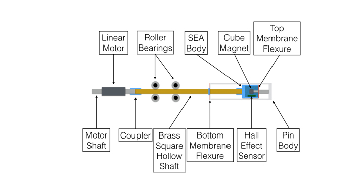
Each pin is a 3D-printed with interchangeable caps. They are 20mmx20mmx120mm. Each pin is mounted on a square hollow tube which rides in custom bearing blocks that constrain all motion except linear travel.
Because the motor and their controllers have a larger cross section than the pins, they could not be assembled in a 2D array directly. Instead, every other motor is staggered, mounted to a lower height, and the tubes for those pins are extended appropriately. The motors, controllers, and bearing blocks are all mounted to lasercut acrylic plates, ten sets in each plate, five “upper” and five “lower. Then five of these plates are mounted side-by-side to form the 50-pin array.
The first version of inForce used Force-Sensitive Resistors (FSRs) to measure the downward force on every pin. This design was mechanically simple, but suffered low controllability. Small changes in pin position resulted in large changes in force, because the force is dependent on the springiness of whatever is applying counterforce to the pins (i.e. the “squishyness” of a user’s hand). To fix this, the second version incorporated springs between the pins and the internal FSRs. This worked well but was mechanically unstable because the pins simply rested on the springs, and had no other constraints.
It was also difficult to calibrate because of the nonlinear response of the FSRs. To solve these problems, I designed several iterations using Series Elastic Actuators for force control that would measure displacement using the proximity of magnets to hall-effect sensors (Allegro A1454). The challenge was to design an SEA mechanism that could fit inside each pin, which is only 20mm square and 120mm tall. These designs worked better, but proved too complicated to manufacture and assemble for all 50 pins.
Each CAN bus on the inForce system connects to an Arduino Teensy 3.2 via a SN65HVD230 CAN transceiver. There are ten arduinos, one for each CAN bus. All arduinos are connected to a single USB hub, which connects to the host computer. Each arduino also has a DIP switch to physically set it’s ID in binary. Each arduinos reads it’s IDs and broadcasts it over USB. This way, the host computer software can determine which arduino controls which pins, even if the arduino USBs are plugged in a different order, or if arduinos are swapped. The host computer software was written in C++ using OpenFrameworks for 3D visualization and
